
TDI Eco-Kit Installation: VW Jetta/Golf (CJAA) & Passat (CKRA)
Tools Required
” _builder_version=”4.27.6″ _module_preset=”default” global_colors_info=”{}”][/tfdt_module_row][tfdt_module_row text1=”13mm Sockets” _builder_version=”4.27.6″ _module_preset=”default” global_colors_info=”{}”][/tfdt_module_row][tfdt_module_row text1=”16mm Sockets” _builder_version=”4.27.6″ _module_preset=”default” global_colors_info=”{}”][/tfdt_module_row][tfdt_module_row text1=”18mm Sockets” _builder_version=”4.27.6″ _module_preset=”default” global_colors_info=”{}”][/tfdt_module_row][tfdt_module_row text1=”10mm Triple-Square” _builder_version=”4.27.6″ _module_preset=”default” global_colors_info=”{}”][/tfdt_module_row][tfdt_module_row text1=”Pliers” _builder_version=”4.27.6″ _module_preset=”default” global_colors_info=”{}”][/tfdt_module_row][tfdt_module_row text1=”Jack Stand” _builder_version=”4.27.6″ _module_preset=”default” global_colors_info=”{}”][/tfdt_module_row][/tfdt_module]
Tools Included
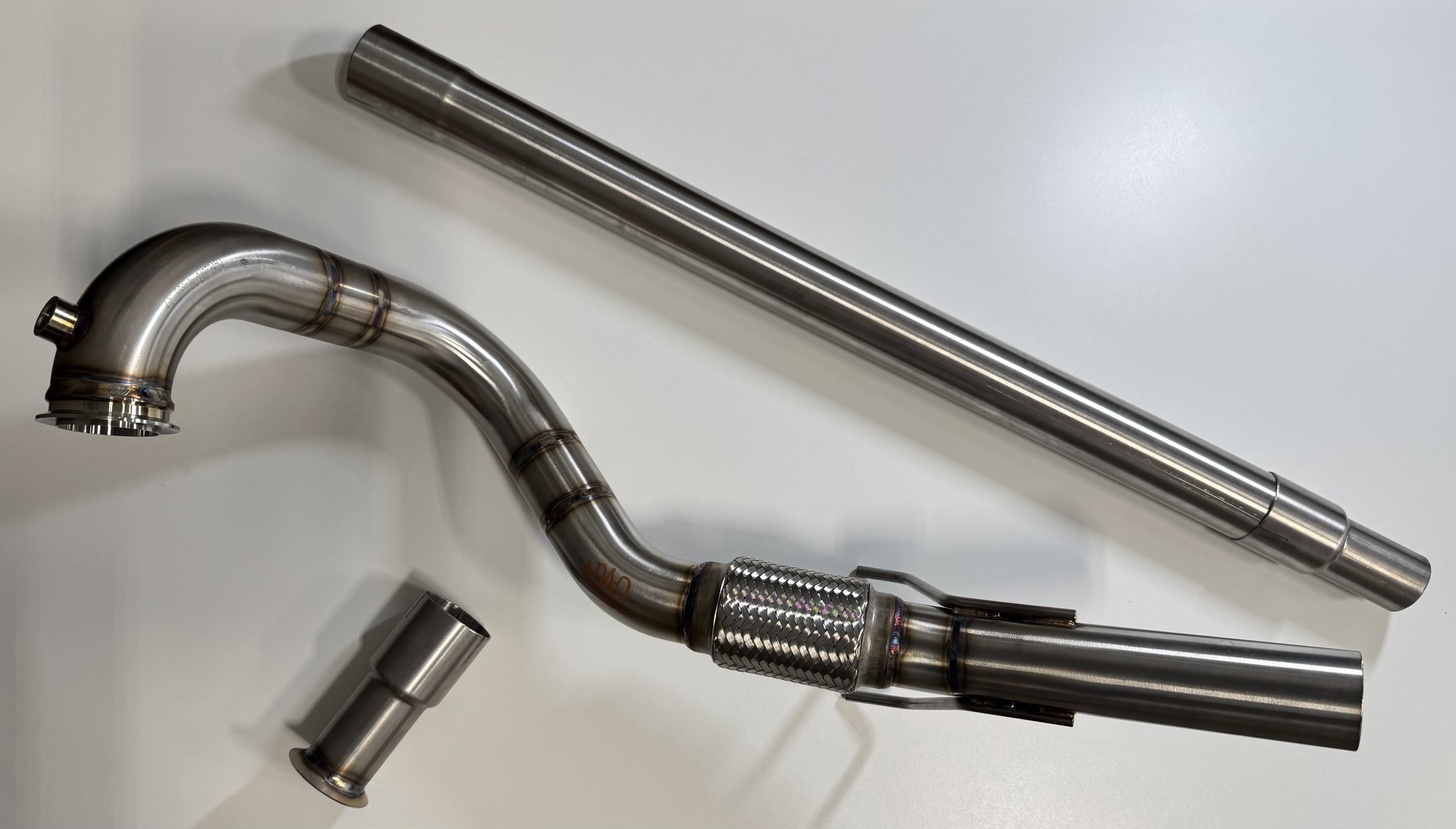
VW & Audi TDI CR140 ECO KIT
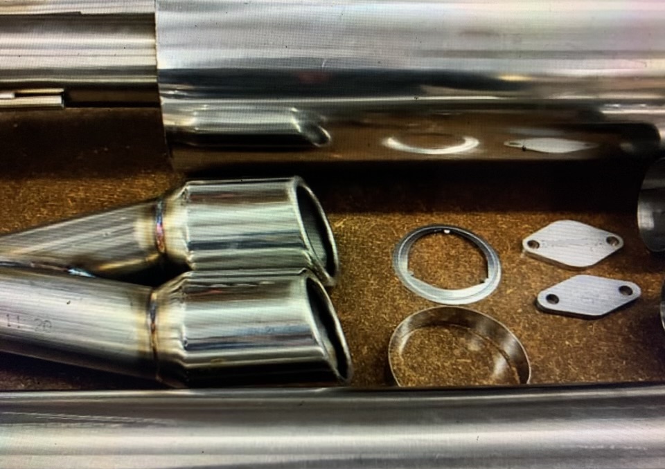
” _builder_version=”4.27.6″ _module_preset=”default” text_orientation=”left” global_colors_info=”{}”][/tfdt_module_row][tfdt_module_row text1=”1x Universal 19mm 90 Degree Plastic Joiner ” _builder_version=”4.27.6″ _module_preset=”default” global_colors_info=”{}”][/tfdt_module_row][tfdt_module_row text1=”1x Medium Blanking Plate” _builder_version=”4.27.6″ _module_preset=”default” global_colors_info=”{}”][/tfdt_module_row][tfdt_module_row text1=”2x Large Blanking Plate” _builder_version=”4.27.6″ _module_preset=”default” global_colors_info=”{}”][/tfdt_module_row][tfdt_module_row text1=”Slip Joint Reducer With Flare
” _builder_version=”4.27.6″ _module_preset=”default” global_colors_info=”{}”][/tfdt_module_row][/tfdt_module]
VW Passat TDI CKRA ECO KIT
Essential Information (Read This First)
Crush/Burn Hazard.

Use jack stands on level ground. Wait 2+ hours for exhaust to cool.
Off-Road Use Only.

Product is not emissions-legal for public roads. Check local laws.
Proper Fitment

Designed for stock vehicles. Verify fitment if your vehicle is already modified.
🛑 CRITICAL SAFETY PRECAUTIONS
Safety First: When working on, under, or around any vehicle, exercise extreme caution.
-
Lifting: If using a lift or jack, always consult your owner’s manual for correct lifting points and specifications. If using a floor jack, you must use rated jack stands.
-
Temperature: Allow the exhaust and engine to cool for at least two hours before starting. Surfaces can cause severe burns.
-
Personal Protection: Always wear safety glasses and work in a well-lit, secure area.
-
Risk: Serious injury or death can occur if standard safety measures are not followed.
⚖️ LEGAL DISCLAIMER & LIABILITY
By installing a Diesel DNA Tuning product, you acknowledge and agree to the following terms:
-
Responsibility: You assume full responsibility for abiding by all local, state, and provincial laws regarding vehicle emissions and operation.
-
Off-Road Use: All TDI exhaust products are intended for off-road/racing use only and may not be used on public roads.
-
Installation: It is the purchaser’s responsibility to follow all provided installation guidelines. Diesel DNA Tuning assumes no responsibility for damages, mechanical/electrical failures, or legal consequences resulting from improper installation, misuse, or abuse of these products.
-
Modifications: These products are designed for stock vehicle applications. If your vehicle is modified, you are responsible for verifying component fitment before beginning installation.
🛠️ INSTALLATION BEST PRACTICES
-
Torque Specs: Always use factory torque specifications and tightening sequences when reinstalling factory fasteners.
-
Tool Integrity: Ensure you are using the correct tools for the job (e.g., proper triple-square and Torx drivers) to avoid stripping bolts.
-
Inspection: Before your first test drive, double-check all connections, clearances, and wiring harnesses for secure placement.
Phase 1: Under the Hood (Engine Bay)
Disconnect battery and remove engine cover.
1) Disconnect the negative battery terminal.
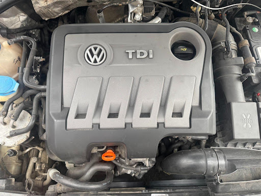
2) Remove the plastic engine cover. (Pull up on the four corners)
Remove and set aside the 1st and 2nd pressure sensors.
3) 1st pressure sensor (passenger side of engine)
(a) Remove the three torx bolts.

(b) Disconnect the electrical connector.
(c) Remove the brackets and set aside.
(d) With pliers, loosen the hose clamps and remove the sensor from the hoses.
(e) Set all these parts aside, they will be reinstalled later.
4) 2nd pressure sensor (rear of engine)

(a) Open up the silver heat wrapping.
(b) Disconnect the electrical connector.
(c) Remove the torx screw securing the sensor bracket to the valve cover.
(d) With pliers, loosen the hose clamp and remove the sensor (with bracket) from the hoses.
(e) Set all these parts aside, they will be reinstalled later.
DPF heat shield removal
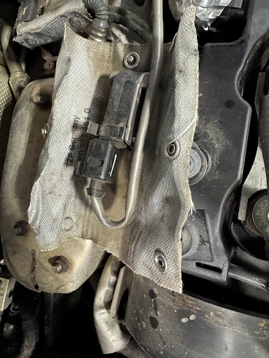
5) On the upper DPF heat shield, remove the 3 nuts (10mm) and remove the heat shield. This will not be reused.
You may reinstall the bracket, sit the sensor in it and plug the electrical connection back in, some people find this to look more organized but it is not not necessary.
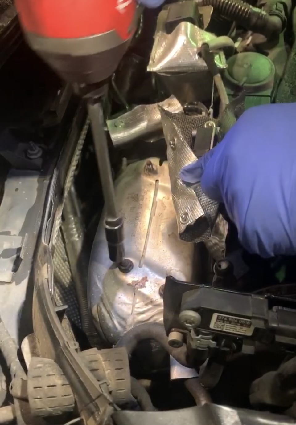
Using a 10mm socket with an extension to remove the three nuts on the CJAA platform.
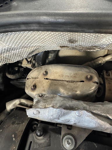
The factory heat shield layout on the CKRA platform. Remove the three 10mm nuts shown.
Disconnect O2 and EGT sensor wires (note the orange and brown connectors near the battery).
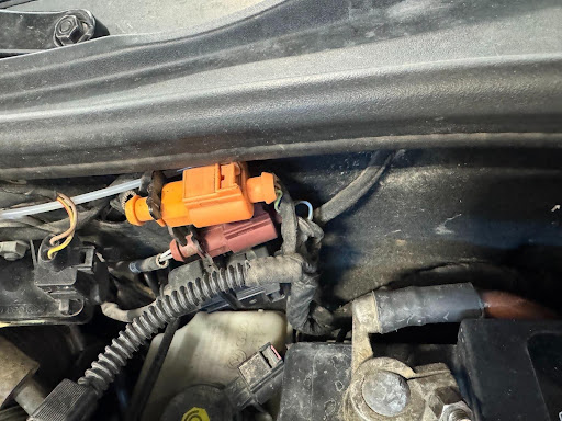
6) Sensor Wires
(a) Free the 3 wires (two EGT and one O2 sensor wires) from the wire guides shown (above).
(b) Disconnect the ORANGE and BROWN electrical connectors next to the battery. The brown connector is in the back, up against the firewall.
They will not be used going forward
(c) Remove silver heat wrap from the oxygen sensor wire. Set aside to reinstall later.
(d) Unscrew the oxygen sensor from the DPF and set aside but do not disconnect from the vehicle.
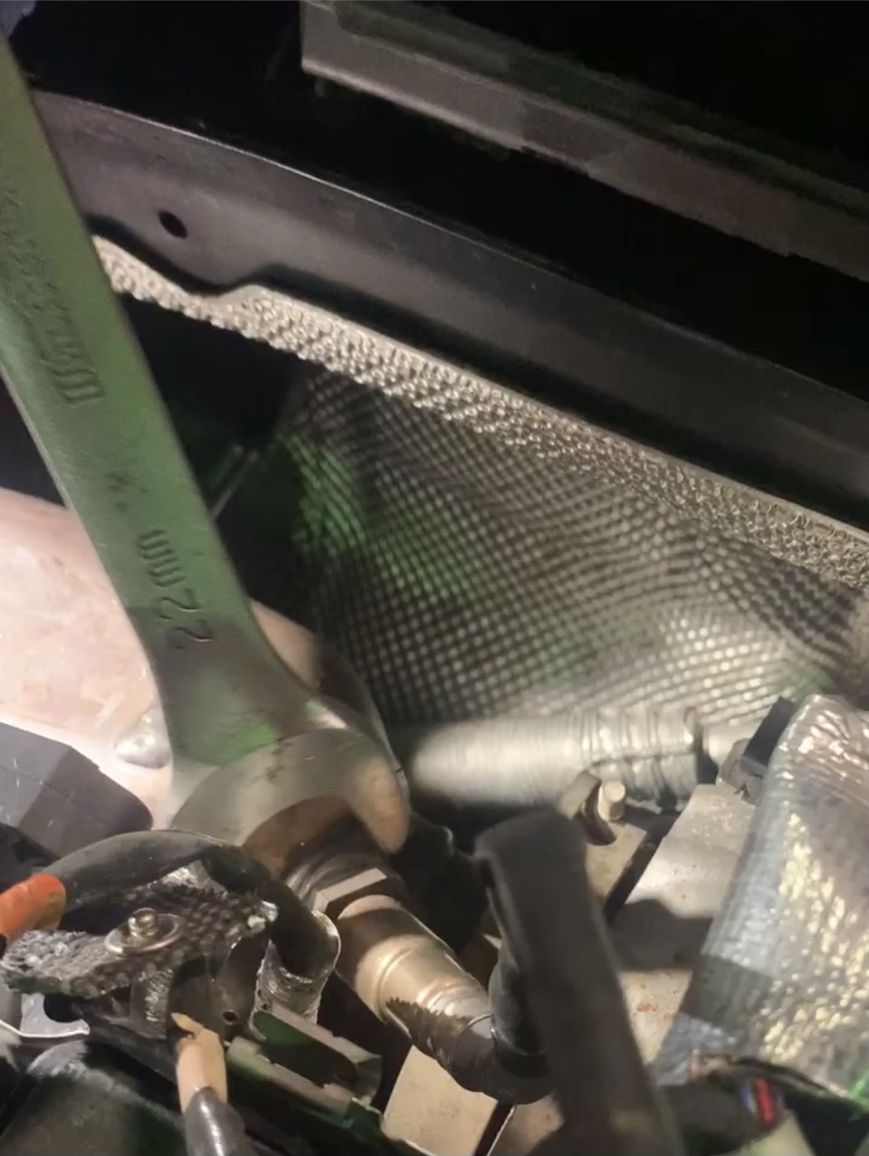
Remove the DPF bracket hex bolt (13mm) and the EGR canister nut (13mm).
7) Using a 13mm socket on an extension, remove the hex bolt on the DPF bracket. This bolt is slightly hidden between the DPF and the engine. Do not discard. This bolt will be reused later.
NOTE: Removal of the EGR cooler is optional, if you do not have a specific reason to remove the EGR cooler we recommend leaving it in place and using the smaller of the plates to block if off.
8) Remove the nut securing the upper bracket of the EGR canister to the turbo.
NOTE: This nut is hard to access. It is best accessed from the top. Reach down between the turbo and firewall to feel for it. Once you locate it, get a short 13mm wrench on it and loosen.
Phase 2: Under the Vehicle (DPF Removal)
Remove skid plate, metal braces, and oxygen sensors.
9) Remove the plastic skid plate from under the engine.
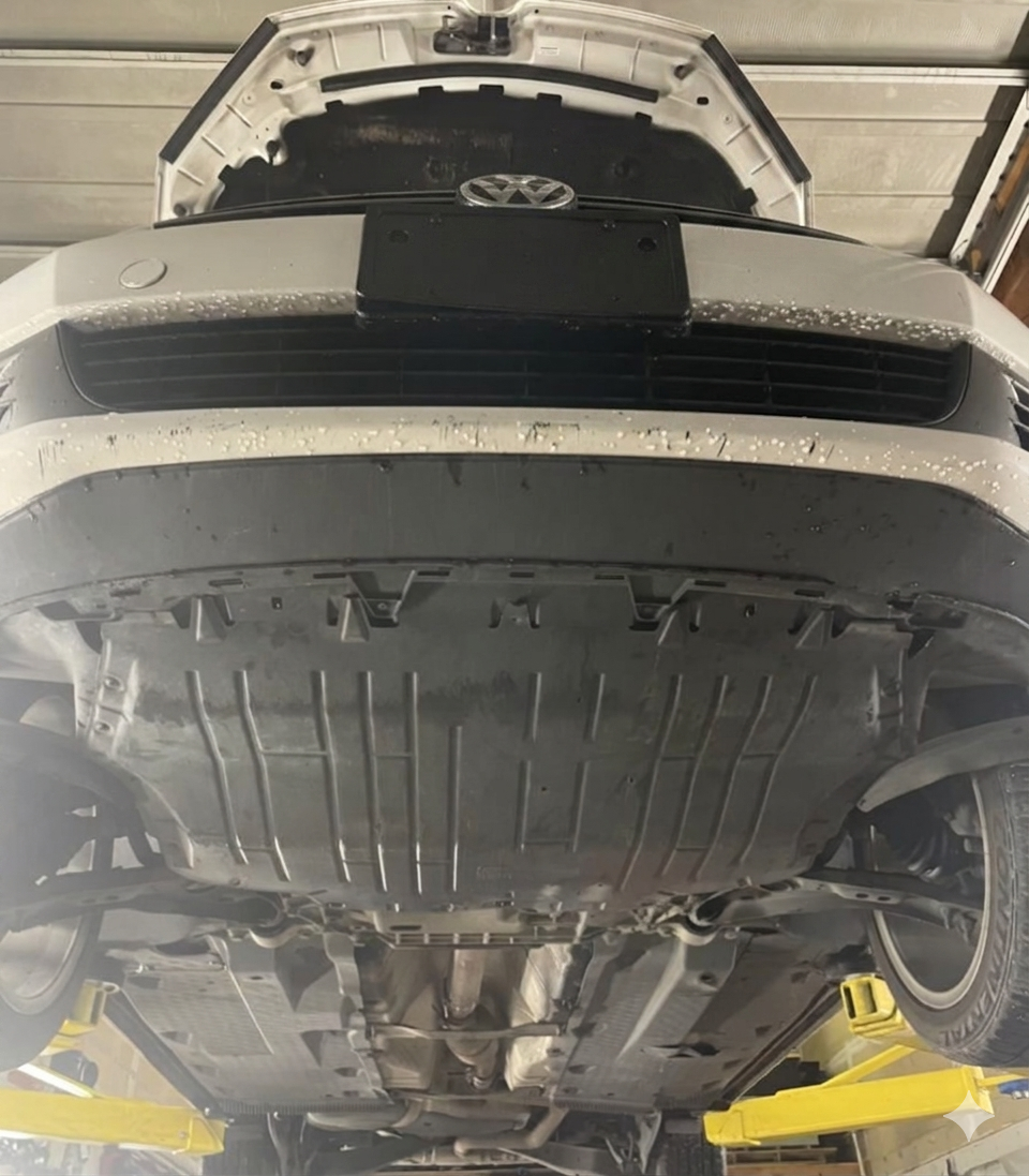
10) Remove the two metal braces from under the exhaust tunnel.
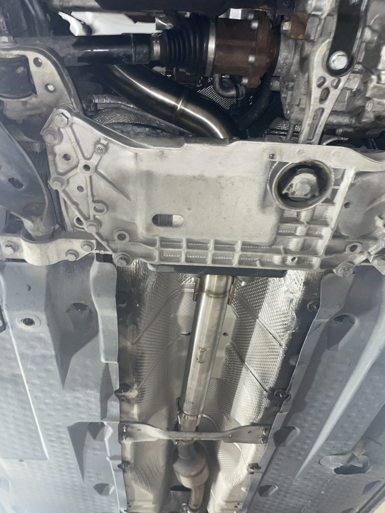
11) Unscrew the oxygen sensor from the exhaust and let it hang down.
Exhaust flap motor
12) Disconnect the motor and remove associated wiring.
a) Remove the heat wrap from the exhaust flap motor and oxygen sensor wires.
(b) Disconnect the exhaust flap motor electrical connector.
(c) Unscrew 4 plastic nuts holding the plastic undercarriage protector to the body.
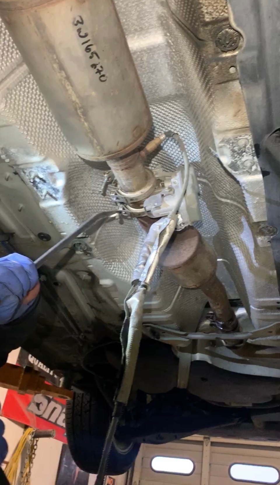
(d) While pulling down on the plastic undercarriage protector, pry the plastic bracket holding the electrical connectors off of the vehicle body. Then disconnect the Orange, Brown, and Black connectors. Remove the Oxygen Sensor and Exhaust Flap wire and set aside. These will not be reinstalled. You will no longer need the plastic bracket, but you can reinstall it if you want and hang the car side of the connectors on it
(e) For the Orange connector, trace the wire back to the EGT sensor in the exhaust below the flex pipe. Remove the wire from all of the metal retaining clips holding it in place.
(f) Apply some grease to the Orange, Brown, and Black open electrical connectors remaining on the car. This will prevent corrosion.
(g) Tuck wires away and reinstall plastic undercarriage protector.
DPF Separation: Loosen the V-band clamps and remove the catalytic converter pipe assembly.
13) Catalytic Converter Pipe Assembly
(a) Loosen the 2 nuts (13mm) on the exhaust band clamp, where the catalytic converter pipe meets the stock cat back exhaust.
(b) With a stand or second set of hands to support the catalytic converter pipe, remove the front most V-band clamp connecting the cats to the DPF pipe. The band clamp is often stuck so you may need to jar it loose with a pry bar and hammer.
(c) With the cat pipe assembly supported, carefully slide the band clamp back, remove the cat pipe assembly and set aside.
Clearance Steps: Remove the axle heat shield and disconnect the passenger side axle (6x 10mm triple-square bolts).
14) Remove the two bolts (13mm) securing the exhaust support to the subframe.
15) Remove the axle heat shield (two 16mm bolts).
16) Remove the six bolts (10mm triple-square) on the passenger side axle.
17) EGR filter canister
a) Remove the small V-band clamp.
b) Remove the two bolts (13mm) on the EGR canister flange.
c) Remove the canister from the vehicle and set aside.
18) On the DPF pipe, just after the flex coupling, unscrew the EGT sensor from the exhaust. Set the sensor aside.
⚠️ SEIZED SENSOR WORKAROUND
Condition: If the EGT sensor is seized into the pipe and cannot be removed.
Solution: You must lower the subframe (6x 18mm bolts) to create the clearance needed to pull the DPF out with the sensor still attached. Remove the six subframe bolts (18mm) that secure the subframe to the frame. The subframe will drop down by about one inch. It will hang from the steering system.
Important: If you choose this route, a professional wheel alignment is required afterward as the subframe may shift slightly.
The "Engine Rock": Remove the dog bone brace bolts to allow the engine to move for DPF clearance.
19) Remove two bolts securing the dog bone brace to the transmission. This will allow the engine to move around a bit. You’ll be able to move the axle out of the way and rock the engine back and forth to access bolts.
Model Note: For CJAA/CBEA models, if the EGT sensor is seized, the subframe may need to be lowered (6x 18mm bolts). Note that this step is often unnecessary for the Passat.
20) Remove the four nuts (13mm) on the bracket securing the DPF to the engine. The bracket will not come out until the DPF is loose.
21) Remove the V-band clamp securing the DPF to the turbo. Volkswagen usually installs this clamp with the bolt facing downwards. If you can’t reach it from the top then you will have to use an allen bit on the end of a long extension to access it. The band clamp is often stuck so you may need to jar it loose with a pry bar and hammer. USE CAUTION! The DPF is now loose.
22) From the top, drop the two EGT wires down alongside the DPF. This way when the DPF comes out the bottom, the wires won’t get caught on anything.
23) Use a jack stand under the front of the transmission to rock the engine forward. This will angle the back of the engine down and away from the firewall, giving you more clearance to remove the DPF.
24) It is now time to remove the DPF. From the bottom, pull the DPF down while rotating it clockwise. The DPF could be rotated 180 degrees when it is finally pulled out through the exhaust tunnel.
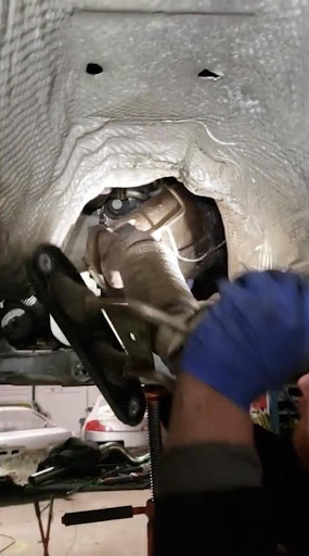
Note: Make sure that the brackets and/or wires are not getting hung up on anything. The bracket can be removed to make it easier. You can slowly inch the DPF out of the tunnel. If you can’t get it out, you can cut the DPF pipe.
25) Remove the rubber and plastic exhaust bracket from the DPF and set aside. It will be reinstalled later.
26) Re-install the axle to the transmission coupler (six triple-square bolts).
Note: Re-install the subframe if you had to loosen it. Try to get the subframe lined up as much as possible in its original location. There are no locating pins to line it up.
Note: You may need to go for a wheel alignment.
Phase 3: Installation of New Hardware
EGR Block Off
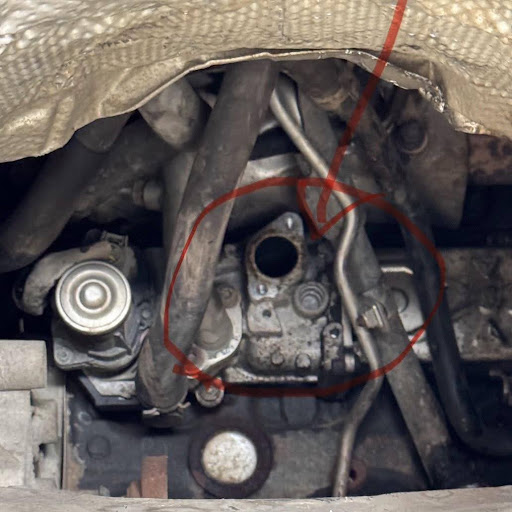
27) Clean surfaces and install the appropriate aluminum block off plates using original gaskets and high-temp silicone.
(a) Carefully clean the gasket surface on the EGR cooler.
(b) Locate the original gasket and two (13mm) bolts from the EGR filter canister. Clean both sides if the gasket.
(c) Apply a thin layer of high temp silicone gasket maker to both sides of the gasket. (we use Permatex 81878 Ultra Copper )
(d) Stick the gasket to the provided aluminum EGR block off plate.
(e) Using the original (two 13mm) bolts, install the aluminum EGR block off plate and gasket onto the back of the engine.
Downpipe
28) Maneuver the new downpipe into the turbo outlet, ensuring the centering sleeve is seated before tightening the V-band clamp.
a) Carefully clean the gasket surface on the turbo outlet.
b) Locate the original Turbo/DPF gasket. Clean both sides of the gasket. Install the gasket to the inlet of the downpipe, over the centering sleeve.
c) From the top of the engine, carefully maneuver the downpipe into place with the centering sleeve slipping into the turbo outlet.
d) Install the original V-band clamp over the downpipe and the turbo outlet flange. Do not fully tighten. It should be snug but you should still be able to rotate the downpipe inside the turbo a little bit.
e) Rotate the downpipe into position so it sits in its most natural direction.
g) Now tighten the V band clamp so it is secure but the downpipe can still rotate if need be. you will want to do the final torque to spec from the top.
Note: The clamp is designed to stretch so it will break before it ever bottoms out. Do not over tighten.
Sensors: Reinstall the primary O2 sensor with anti-seize.
29) Reinstall Sensors
(a) Apply a small amount of anti-seize to the threads of the O2 sensor.
(b) Reinstall the primary O2 sensor into the downpipe.
(c) Optional: Reinstall the pressure sensors with their brackets to the engine as they originally were. Make sure that the sensors are connected electrically. For the sensor on the passenger side of the engine, there will be no hoses going to it. You will just leave the pressure ports open to atmosphere. For the pressure sensor on the rear of the engine there will be only one hose available. You will connect this hose to the appropriately sized pressure port. The other port will stay open to atmosphere.
d) Install the plastic and rubber exhaust bracket onto the subframe as it originally was.
e) Put the front half of the midpipe up into position with the 13 mm hex bolts as it originally was
h) Install the provided reducer with the flare on it on the rear of the downpipe. Re-use the narrowest v-band clamp to connect it to flare on the secondary muffler after you remove the exhaust flap.
j) Make sure that everything is lined up nicely and fully tighten.
30) Reinstall the two metal braces under the exhaust tunnel.
31) Reinstall the axle heat shield.
32) Reinstall the two bolts into the transmission dog bone brace.
33) Reinstall the plastic skid plate under the engine. Reinstall the plastic engine cover
34) Reconnect the negative battery terminal.
35) Enjoy.